Javascript Tree Menu by Deluxe-Tree.com ValuDrive 12-48 Vdc BLDC Brushless DC Control

Controllers
GreenDrive 12-48 Vdc Brushless DC Control
GreenDrive 12-48 Vdc Brushless DC Control Specifications:
Voltage: 12-45Vdc for Analog and PWM Control Methods
12-48 Vdc with Hall Output
Operating Modes: External, Open Loop Speed, Closed Loop Speed,
Torque (Open Loop), Preset Speed
Control Methods: Analog, PWM, PWM & Direction
Note:  These control methods are available with or without an internally supplied 5Vdc power supply.
Encoder Options: 100, 250, 256 w/ index, 400, 1000 line available
Protection: Current Limit
Under Voltage
Integral Design: Fits on the back of our HST23 and Dynamo Brushless DC motors
GreenDrive 12-48 Vdc Brushless DC Control Inputs/Outputs:

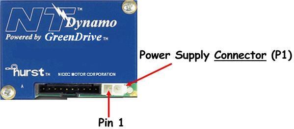
Motor Power Supply Connections:

Pin Number Description Input/Output Notes
1 +DC Input 12-45Vdc for Analog and PWM Control Methods
12-48 Vdc with Hall Output (Feedback Board Only)
2 GND Input  
       

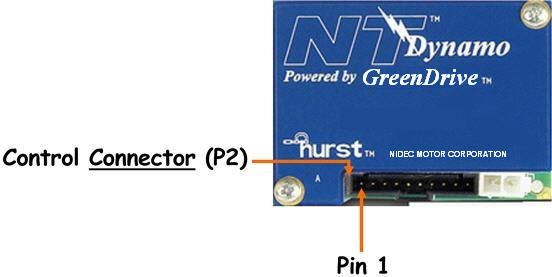
Control Connections:

Pin Number Description Input/Output Notes
1 Tachometer Output Speed Output – 15 Pulses/Revolution (PPR) for Dynamo and 9 PPR for HST23 at TTL Level
(0 to 5 Vdc) and 50% Duty Cycle
2 Speed/Torque Input Only used for Analog Control Method
3 PWM Input 0% duty cycle minimum command
100% duty cycle maximum command
Used with Direction Input pin (Pin 7)
4 Encoder Channel B Output Speed and Direction Output – PPR based on encoder line count at TTL Level (0 to 5 Vdc) and 50% Duty Cycle; No output if encoder not present
5 Encoder Channel A Output Speed and Direction Output – PPR based on encoder line count at TTL Level (0 to 5 Vdc) and 50% Duty Cycle; No output if encoder not present
6 Direction Output 0 Vdc output = clockwise lead end
5 Vdc output = counter-clockwise lead end
Can be used in conjunction with Tachometer output (Pin 1) to determine speed and direction
7 Direction /
PWM & Direction
Input Direction -
  • Clockwise Lead End = Low Level (GND)

  • Counter-Clockwise Lead End = High Level (5Vdc)

  • Used in conjunction with PWM (Pin 3) and Speed/Torque (Pin 2)
    PWM & Direction -
  • 0% Duty Cycle maximum command in the counter-clockwise direction lead end
  • 50% Duty Cycle minimum command
  • 100% Duty Cycle maximum command in the clockwise direction lead end
  • 8 Enable Input Low Level signal (0 Vdc) enables drive
    9 GND -- Return path for +5 VDc (Pin 10)
    10 +5 Vdc Input / Output Input - User supplied 5Vdc
    Output - Optional Integral 5Vdc supply
    Addtional Information:
    Flexible – Reliable – and Affordable. 

    External- The External Control Module (commutation board) simplifies the connection of an external motor drive to the Dynamo motor by providing the user with a standard set of hall signals, numerous encoder options, and a high current connector for the motor phase windings.  The module is compatible with external motor drives using a 10 to 48Vdc power supply.

    The external Control Module provides a standard system for rotor position sensing required by most brushless motor drives.  Three hall devices spaced 120 electrical degrees apart, sense a magnetic disk which is synchronized to the rotor of the motor.  The hall signals can be used to provide inexpensive speed feedback to the motor drive, or for more precise control a wide array of integral, two channel quadrature encoder options are available.  The quadrature nature of an encoder allows the user to determine the direction of motor rotation as well as the speed.

    Analog- The Analog Open Loop Motor Control converts DC input voltage into three phase waveforms.  The control performs 2-quadrant commutation when an analog control signal is supplied.  The control is compatible with 20Vdc to 36Vdc power supplies.  The flexible customer interface allows for the following input signals:

    • Analog (0-5Vdc)
    • Contact Closure for Start/Stop and Fwd/Rev

    Open loop speed control is accomplished by the user supplying a 0-5Vdc analog input or by using the controls 5Vdc output with a potentiometer.  Contact closures (PLC’s or relays) can be substituted for standard switches.  For cost sensitive applications requiring minimal speed feedback a tachometer output can be accessed.  The tachometer output is based on the signals from the hall devices used to commutate the motor.  The tachometer signal is an open collector output with a 1K ohm resistor in series.  The output is 30 pulses per revolution (ppr).  The signal pulses low for 300ns minimum, 600ns typical.

    PWM- The PWM Motor Control converts DC input voltage into three phase waveforms.  The control performs 4-quadrant commutation when a PWM control signal is supplied.  The control is compatible with 20Vdc to 36Vdc power supplies.  The flexible customer interface allows for the following input signals:

    • PWM
    • Contact Closure for Start/Stop

    Open loop speed control is accomplished by the user supplying a logic level PWM input.  Contact closures (PLC’s or relays) can be substituted for standard switches.  For cost sensitive applications requiring minimal speed feedback a tachometer output can be accessed.  The tachometer output is based on the signals from the hall devices used to commutate the motor.  The tachometer signal is an open collector output with a 1K ohm resistor in series.  The output is 30 pulses per revolution (ppr).  The signal pulses low for 300ns minimum, 600ns typical.  For applications requiring more precise control a Hurst encoder can be added internally to the control for true closed loop operation.

    GreenDrive 12-48 Vdc Literature: